Search This Blog

Showing posts with label Arduino. Show all posts

Friday, 21 April 2023

IR (infrared ) sensor

 An IR sensor, short for Infrared sensor, is a device that is capable of detecting infrared radiation or heat. It can measure the amount of infrared radiation emitted by an object and convert it into an electrical signal, which can be used for various purposes. IR sensors are widely used in a variety of applications, including remote controls, security systems, and temperature sensors.


How does an IR sensor work?

An IR sensor works by detecting the amount of infrared radiation emitted by an object. Every object emits some level of infrared radiation, which can be detected by an IR sensor. An IR sensor typically consists of an IR emitter and an IR receiver. The emitter emits a beam of infrared radiation, which is then reflected back by the object being detected. The receiver then detects the reflected infrared radiation and converts it into an electrical signal.
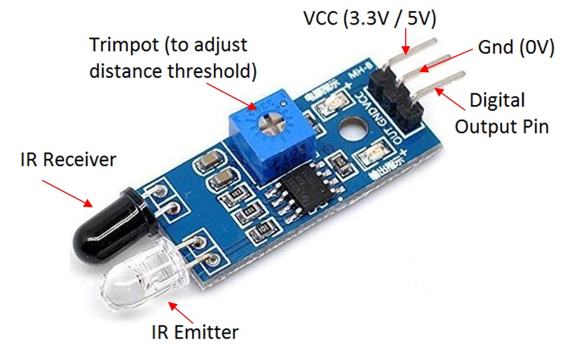


Types of IR sensors

There are two main types of IR sensors: active and passive.

Active IR sensors emit infrared radiation and then detect the radiation that is reflected back. This type of IR sensor is commonly used in proximity sensors, which can detect the presence of an object and measure the distance between the sensor and the object.

Passive IR sensors, on the other hand, detect the infrared radiation emitted by an object. This type of IR sensor is commonly used in temperature sensors and motion detectors.

Applications of IR sensors

IR sensors have a wide range of applications. Some of the most common applications include:

  1. Remote controls: IR sensors are commonly used in remote controls for TVs, DVD players, and other electronic devices. The sensor detects the infrared radiation emitted by the remote control and uses it to control the device.

  2. Security systems: IR sensors are commonly used in security systems to detect the presence of intruders. The sensor detects the infrared radiation emitted by a person's body heat and triggers an alarm if the person is detected.

  3. Temperature sensors: IR sensors can be used to measure the temperature of an object without touching it. This makes them ideal for use in applications where contact with the object is not possible or desirable.

  4. Proximity sensors: IR sensors can be used to detect the presence of an object and measure the distance between the sensor and the object. This makes them ideal for use in robotics and automation applications.

Conclusion

IR sensors are versatile devices that can be used in a variety of applications. They work by detecting the amount of infrared radiation emitted by an object and converting it into an electrical signal. IR sensors can be used in remote controls, security systems, temperature sensors, and proximity sensors, among other applications. As technology continues to advance, we can expect to see even more applications for IR sensors in the future.

obstacle avoidance robot using arduino

 Here is the code for making a obstacle avoidance robot using :-

1) l298n motor driver 
2) arduino (any)
3)servo  motor (optional)
4) 2 or 4 dc motors and wheels
5)jumper cables if (needed )
6) breadboard if (needed) 


// Motor driver pins

int ENA = 3; int ENB = 5; int IN1 = 2; int IN2 = 4; int IN3 = 6; int IN4 = 7; // Servo pin int servoPin = 9; // Ultrasonic sensor pins int trigPin = 10; int echoPin = 11; // Distance variables long duration; int distance; void setup() { // Set motor driver pins as outputs pinMode(ENA, OUTPUT); pinMode(ENB, OUTPUT); pinMode(IN1, OUTPUT); pinMode(IN2, OUTPUT); pinMode(IN3, OUTPUT); pinMode(IN4, OUTPUT); // Set servo pin as output pinMode(servoPin, OUTPUT); // Set ultrasonic sensor pins pinMode(trigPin, OUTPUT); pinMode(echoPin, INPUT); // Start serial communication Serial.begin(9600); } void loop() { // Rotate servo to scan area for obstacles for (int i = 0; i <= 180; i += 5) { int angle = map(i, 0, 180, 0, 179); digitalWrite(servoPin, HIGH); delayMicroseconds(500 + angle * 5); digitalWrite(servoPin, LOW); delay(30); duration = pulseIn(echoPin, HIGH); distance = duration * 0.034 / 2; if (distance < 30) { // If obstacle detected, stop and turn digitalWrite(ENA, LOW); digitalWrite(ENB, LOW); digitalWrite(IN1, LOW); digitalWrite(IN2, LOW); digitalWrite(IN3, LOW); digitalWrite(IN4, LOW); delay(500); digitalWrite(ENA, HIGH); digitalWrite(ENB, HIGH); digitalWrite(IN1, HIGH); digitalWrite(IN2, LOW); digitalWrite(IN3, LOW); digitalWrite(IN4, HIGH); delay(1000); } } // Move forward if no obstacles detected digitalWrite(ENA, HIGH); digitalWrite(ENB, HIGH); digitalWrite(IN1, HIGH); digitalWrite(IN2, LOW); digitalWrite(IN3, HIGH); digitalWrite(IN4, LOW); delay(500); }

This code uses a servo motor to scan the area for obstacles and an ultrasonic sensor to measure the distance to any obstacles. If an obstacle is detected within 30 cm, the robot stops and turns for 1 second before continuing to move forward. If no obstacles are detected, the robot moves forward. The L298N motor driver is used to control the two motors.


Sunday, 29 November 2020

DIY digital clock at home|| how to make a digital clock||Lucifer||the robotics guy

Code for the Arduino 👇 

// set current time by editing the values at line 16 and 17
const int clock = 7;
const int data = 8;
uint8_t digits[] = { 0x3f, 0x06, 0x5b, 0x4f, 0x66, 0x6d, 0x7d, 0x07, 0x7f, 0x6f };
void setup()
{
  setupInterrupt();
  pinMode(clock, OUTPUT);
  pinMode(data, OUTPUT);
  start();
  writeValue(0x8c);
  stop();
  write(0x00, 0x00, 0x00, 0x00);
}
byte tcnt2;
  unsigned long int setMinutes = 22;
  unsigned long int setHours = 15;
  unsigned long time = (setMinutes * 60 * 1000) + (setHours * 3600 *1000);
void setupInterrupt()
{
  TIMSK2 &= ~(1<<TOIE2);
  TCCR2A &= ~((1<<WGM21) | (1<<WGM20));
  TCCR2B &= ~(1<<WGM22);
  ASSR &= ~(1<<AS2);
  TIMSK2 &= ~(1<<OCIE2A);
  TCCR2B |= (1<<CS22) | (1<<CS20); 
  TCCR2B &= ~(1<<CS21);
  tcnt2 = 131;
  TCNT2 = tcnt2;
  TIMSK2 |= (1<<TOIE2);
}
ISR(TIMER2_OVF_vect) {
  TCNT2 = tcnt2;
  time++;
  time = time % 86400000;
}
void loop()
{
  unsigned long t = (unsigned long)(time/1000);
  uint8_t minutes = (byte)((t / 60) % 60);
  uint8_t hours = (byte)((t / 3600) % 24);
  uint8_t seconds = (byte)(t % 60);
    write(digits[hours / 10], digits[hours % 10] | ((seconds & 0x01) << 7), digits[minutes / 10], digits[minutes % 10]);
}
void write(uint8_t first, uint8_t second, uint8_t third, uint8_t fourth)
{
  start();
  writeValue(0x40);
  stop();
  start();
  writeValue(0xc0);
  writeValue(first);
  writeValue(second);
  writeValue(third);
  writeValue(fourth);
  stop();
}
void start(void)
{
  digitalWrite(clock,HIGH);
  digitalWrite(data,HIGH);
  delayMicroseconds(5);
  digitalWrite(data,LOW);
  digitalWrite(clock,LOW);
  delayMicroseconds(5);
}
void stop(void)
{
  digitalWrite(clock,LOW);
  digitalWrite(data,LOW);
  delayMicroseconds(5);

  digitalWrite(clock,HIGH);
  digitalWrite(data,HIGH);
  delayMicroseconds(5);
}
bool writeValue(uint8_t value)
{
  for(uint8_t i = 0; i < 8; i++)
  {
    digitalWrite(clock, LOW);
    delayMicroseconds(5);
    digitalWrite(data, (value & (1 << i)) >> i);
    delayMicroseconds(5);
    digitalWrite(clock, HIGH);
    delayMicroseconds(5);
  }
  digitalWrite(clock,LOW);
  delayMicroseconds(5);
  pinMode(data,INPUT);
  digitalWrite(clock,HIGH);
  delayMicroseconds(5);
  bool ack = digitalRead(data) == 0;
  pinMode(data,OUTPUT);
  return ack;
}

Circuit diagram 👇👇👇
circuit diagram 🔝🔝🔝

interfacing ph sensor with arduino

You will need to connect the pH sensor to the Arduino board and configure the pins accordingly. Refer to the documentation of your pH se...